2.4. Industrial I/O (Example of a subsection within Industrial I/O)
Your gateway features up to four industrial I/O expansion cards in order to support RS-232 (2-wire), RS-485 (half-duplex), CAN bus, or additional digital input/output channels. The following table illustrates industrial I/O functions and relevant ordering codes:
FUNCTION |
I/O SLOT A |
I/O SLOT B |
I/O SLOT C |
I/O SLOT D |
|---|---|---|---|---|
RS-232 (2-wire) |
ARS232 |
BRS232 |
CRS232 |
— |
RS-485 (half-duplex) |
ARS485 |
BRS485 |
CRS485 |
— |
CAN bus |
— |
— |
CCAN |
— |
Digital I/O (4x DI, 4x DO) |
— |
— |
— |
DDIO |
2.4.1. CAN Bus
The device features up to 2 CAN 2.0B ports implemented with the processor’s CAN controller. Note that the main CAN bus is always available, regardless of I/O module configuration. The second CAN bus is available if the expansion I/O module is installed.
2.4.2. RS-232
The RS-232 function is implemented with the MAX3221 (or compatible) transceiver interfaced with the i.MX8M Plus processor UART ports. The key characteristics of this unit are:
Support for TX/RX only
Galvanic isolation from the main unit
Programmable baud rate of up to 250 kbps
2.4.3. RS-485
The RS-485 function is implemented with the MAX13488 (or compatible) transceiver interfaced with the i.MX8M Plus processor UART ports. The key characteristics of this unit are:
2-wire, half-duplex operation
Galvanic isolation from the main unit
Programmable baud rate of up to 3 Mbps
Software-controlled 120Ω termination resistor
2.4.4. Digital inputs and outputs
Four digital inputs are implemented with the CLT3-4B digital termination in accordance with EN 61131-2. Four digital outputs are implemented with the VNI4140K solid-state relay in accordance with EN 61131-2. The key characteristics of this system are:
Designed for 24V PLC applications
Galvanic isolation from main unit and other I/O modules
Maximum current output of 0.5A per channel for digital outputs
FEATURE |
MIN. |
TYP. |
MAX. |
UNIT |
|---|---|---|---|---|
External input voltage (24V_IN) |
12 |
24 |
30 |
V |
Input voltage: LOW level ($V_{IL}$ Max.) |
4 |
V |
||
Input voltage: HIGH level ($V_{IH}$ Min.) |
6 |
V |
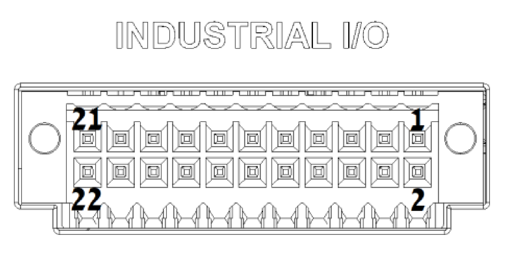
2.4.5. Industrial I/O terminal block
All industrial I/O module signals are routed to a terminal block. The pinout is determined by the configuration of I/O modules installed in the system.
FEATURE |
DESCRIPTION |
|---|---|
Connector Type |
22-pin dual-raw plug with push-in spring connections |
Locking Mechanism |
Screw flange |
Wire cross-section |
AWG 20 - AWG 30 |

Industrial I/O: Terminal Block Pinout
I/O MODULE |
PIN |
SIGNAL |
ISOLATED POWER DOMAIN |
|---|---|---|---|
A |
1 |
RS232_TXD / RS485_POS |
1 |
— |
2 |
CAN_L |
1 |
A |
3 |
RS232_RXD / RS485_NEG |
1 |
— |
4 |
CAN_H |
1 |
A |
5 |
ISO_GND_1 |
1 |
B |
6 |
RS232_RXD / RS485_NEG |
2 |
B |
7 |
RS232_TXD / RS485_POS |
2 |
B |
8 |
ISO_GND_2 |
2 |
D |
9 |
IN0 |
3 |
D |
10 |
IN1 |
3 |
D |
11 |
IN2 |
3 |
C |
12 |
RS232_TXD / RS485_POS / CAN_H |
3 |
D |
13 |
IN3 |
3 |
C |
14 |
RS232_RXD / RS485_NEG / CAN_L |
3 |
D |
15 |
OUT0 |
3 |
D |
16 |
OUT1 |
3 |
D |
17 |
OUT3 |
3 |
D |
18 |
OUT2 |
3 |
D |
19 |
24V_IN |
3 |
D |
20 |
24V_IN |
3 |
C/D |
21 |
ISO_GND_3 |
3 |
C/D |
22 |
ISO_GND_3 |
3 |